Spanning-Tree Protocol
can exist between two devices (switches). Multiple active paths between devices cause loops in the network. STP is a layer 2 link management protocol that provides redundancy while avoiding network loops.
Loops are formed because the parallel switches (or bridges) do not know each other. If there is a loop in the network, end stations may receive duplicate messages. Switches can also learn end station MAC addresses on multiple Layer 2 interfaces. These conditions result in an unstable network, raising device performance with garbage frames (infinitely duplicated frames).
Ethernet alone is susceptible to Layer 2 loops because of its original design. All active interfaces on the switches could cause loops, especially with unknown unicast or broadcast frames. Let’s look at two simple topologies that, however simple their design, ethernet alone would cause loops:
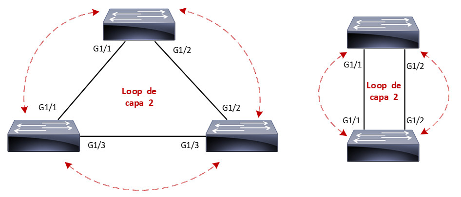
In the above topologies, all switch interfaces are ready to forward incoming frames, causing an infinite loop for each incoming frame. Here is where spanning-tree becomes very important.
STP provides the mechanism for switches to know each other and negotiate a loop-free path through the network. STP achieves its goal by blocking specific ports through its algorithm to avoid these loops. Let’s look at the same topologies with STP active:
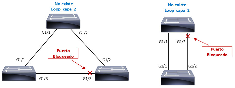
With STP, loops are discovered on redundant links before they are available for use, and these redundant links are effectively blocked to prevent loops from forming. In the case of redundant links, switches can be aware that a link that is disabled (port blocked) for loop prevention has to be activated quickly in the event of a failure on an active link.
Spanning-Tree types
There are three open STP standards that different manufacturers can include in their equipment:
- Common Spanning-Tree (IEEE 802.1D)
- Single STP instance per switch
- Rapid Spanning-Tree (IEEE 802.1W)
-
Significantly reduces 802.1D convergence times.
-
Remains only a single instance of STP
-
- Multiple Spanning-Tree (IEEE 802.1S)
- One STP instance per VLAN group. The number of groups is limited by the characteristics of each device.
The Cisco STP protocols are compatible, but with certain variations, for example, PVST+ is equivalent to Common Spanning-Tree, and Rapid PVST+ corresponds to Rapid Spanning-Tree, in summary, this is:
- Per-VLAN Spanning-Tree Plus (PVST+)
- One STP instance per VLAN
- Operates on ISL and 802.1Q trunks
- Developed to operate with third-party switches.
- Rapid Per-VLAN Spanning-Tree Plus (Rapid PVST+)
- One instance of STP per VLAN.
- Reduction of PVST+ convergence times.
- Multiple Spanning-Tree (IEEE 802.1S)
- No change, cisco switches use the IEEE standard.
In the beginning, cisco used PVST (Per-VLAN Spanning-Tree) very similar to PVST+, but it only worked with ISL trunks. PVST had a disadvantage because ISL is proprietary to cisco and is not compatible with other manufacturers, so PVST was upgraded to PVST+.
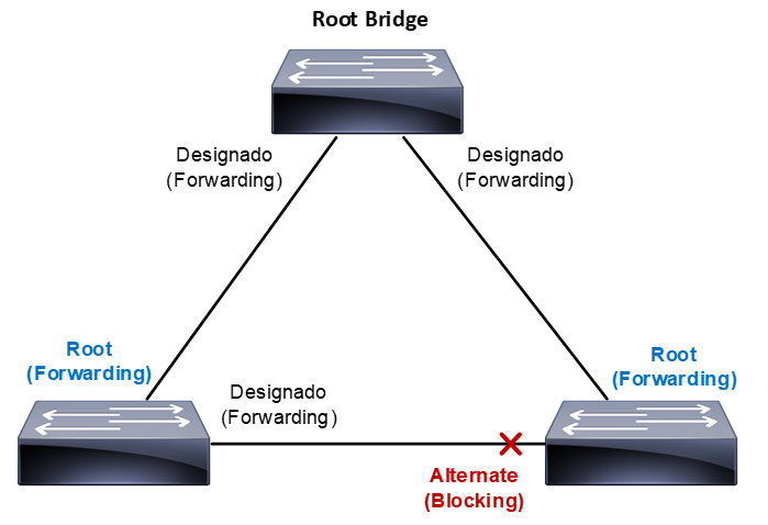
The STP calculation in the switches assigns the following roles to the ports:
- Root: Port ready to forward frames with the best path to the root bridge.
- Designated: Port ready for frame forwarding for each LAN segment or collision domain.
- Alternate: Blocked port with an alternate path to the root bridge different from the root port.
- Backup: Blocked port with an alternate path to the same switch. Redundant links between two switches.
Each role can transit between different STP states: disable, blocking, listening, learning and forwarding.
Let’s start with understanding the operation of Common Spanning-Tree (IEEE 802.1D), the assignment of roles and state of the ports in the switches to achieve a topology free of Layer 2 loops.
The spanning-tree algorithm chooses a switch as a reference point, which it calls the “root bridge”; once the “root bridge” is designated, the other switches in the network calculate the best path to it. If a switch has more than one path available to reach the root bridge, the STP algorithm leaves only one active and blocks the rest to avoid Layer 2 loops.
Switches participating in STP exchange BPDU (Bridge Protocol Data Unit) messages to choose the root bridge through their Bridge ID. The switch with the lowest Bridge ID is elected as the root bridge.
The Bridge ID is an 8-byte value containing:
- Bridge priority (2 bytes): it is a value from 0 to 65535 (Default value is 32768). The value can only be increased or decreased in steps of 4096.
- MAC Address (6 bytes): MAC address of the switch.
The lowest MAC address is used as the tie breaker if the bridge priority value is equal on the switches. BPDUs are sent to the STP Multicast MAC address 01-80-c2-00-00-00-00.
There are two types of BPDUs:
-
Configuration BPDU: used for loops-free network calculation with STP.
- Topology Change Notification (TCN) BPDU: used to announce network topology changes.
By default, BPDUs are sent every 2 seconds, and only the root bridge creates the configuration BPDUs; the other switches only forward these BPDUs by adding their Bridge ID.
Once the root bridge is chosen, STP must calculate a network without loops; for this, it assigns roles and states to the ports of each switch based on costs; in fact, STP uses the cost concept to determine many things.
Each port of a switch has a path cost that depends on its bandwidth; the higher the bandwidth, the lower the path cost; let’s see the most common values used by STP:
| Bandwith | Path Cost |
| 10 Mbps | 100 |
| 100 Mbps | 19 |
| 1 Gbps | 4 |
| 10 Gbps | 2 |
Based on the costs that STP uses, ports can have the following roles: root, designated, alternate, and backup. They can also pass through the disabled, blocking, listening, learning, or forwarding states.
Let’s see a simple topology of how the port roles and states could be assigned:
In the following articles, we will see how the roles are assigned and the transition of the STP states we have mentioned.